|
|

|
| Chapter
7: Motive Power (Conversion) |
| |
| In this chapter I will describe some further steps in acquiring additional motive power for Grindham Shed. There is an exsiting fleet of OO locomotives built before I changed to P4, and which can be converted to run on the new layout. |
| |
| Introduction |
| |
| Subjects for conversion are from two possible sources - locomotives previously built in OO and ready-to-run items. I have a ready stock of the former, but for this section I will look mainly at the latter. In the past, ready-to-run items were often of dubious quality, many compromises being made for ease of production. The range of excellent detailing parts means that even some of the mediocre offerings from the past can be turned into something reasonable; today's quality appears so good that - wheels aside - little would seem to be required for many models. I will start with conversion of a relatively straightforward 0-6-0 tank engine - the ubiquitous GWR "Pannier" - orginally produced by Mainline sometime, I guess, in the 1980's. |
|
| The Candidate |
| |
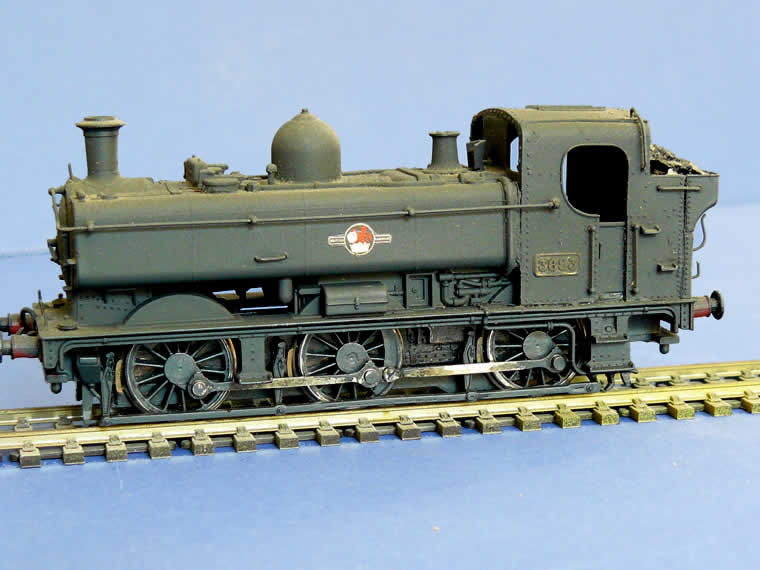 I selected this old Mainline OO Pannier tank for conversion as, many years ago, I replaced the cab with the later "8750" style cab using Alan Gibson components; at the time there was no ready-to-run alternative and these were far more numerous than the earlier 57XX type represented by the Mainline offering. Otherwise, it was a pretty fair model by contemporary standards, so a few cosmetic refinements such as lamp irons and the fire iron brackets were added, and it was repainted to a more weather-beaten state and given an appropriate number. However, the chassis is original and to make the locomotive suitable for use on Grindham Shed, it must be converted to P4.
For this I elected to use a Perseverance chassis kit partly because I had one in "the stores" and partly because I am familiar with them, having used them successfully on other projects. These are of the beam type, as will become apparent as the work progresses The new frames will be fitted with Alan Gibson GW pattern 4ft 7½in wheels |
|
| Frame Components |
| |
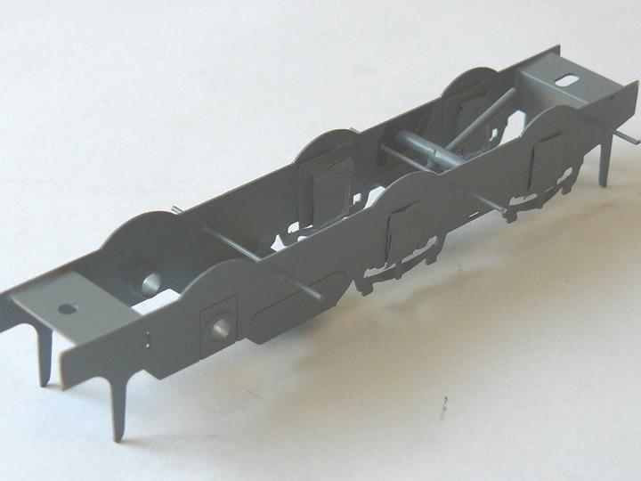
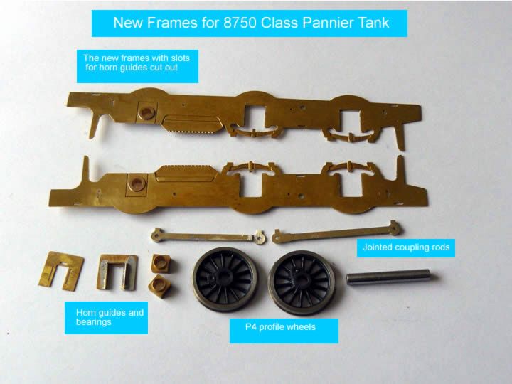 This shows the main components for the new frames - I have only shown samples of wheels etc, to save space.
The first job, after removing the items from the fret, was to cut out the slots in the frames that will take the horn guides, using the etched lines as a guide. You can see these lines around the rear axle, which will be fixed, so the slot does not need cutting. The picture shows one of the hornguides before and after the addition of the bearing faces; the brass bearings supplied with the kit are alongside. Before taking the photograph, I soldered the two layers of each half of the coupling rods together; these are a key component in setting up the frames for assembly as will be explained below. The picture also shows a pair of P4 wheels - the fine profile is in stark contrast to those on the original Mainline chassis in the previous photograph. They have yet to have the crank pins fitted. Not included in this picture are the components for the brakes and brake rigging, the compensation beam or the spacers that will be used when erecting the frames. |
|
| Frame Assembly |
| |
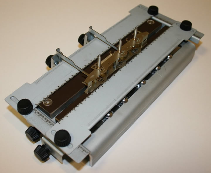 The traditional method of assembly is to erect the frames with appropriate spacers and then hold the hornguides and the bearings in place with sprung jigs, spaced correctly by the coupling rods, while the guides are soldered in place. However, a recent innovation - the Avonside Chassis Jig - offers an alternative method, and this is what I have used.
With this, the coupling rods are used to set up the correct axle spacing in the jig; the jig is then used to set the horn guides and bearings correctly in the frames, making soldering them accurately in place very much easier. The jig can then be used to assemble the frames and spacers as seen in the accompanying illustration. The jig is designed to give very precise adjustment of the axle positions which should ensure perfect alignment of the axles and the coupling rods and ensure the frames are erected square to the axles - essential for a reliable and free running chassis; it can be used to build frames for up to 10 coupled wheels. Parts are also provided to set up frames for tenders and bogies using 2mm axles. The jig is not cheap, and is not essential, but it is a worthwhile investment in terms of ease and accuracy. It is a remarkable innovation of which the designer should be justly proud. Usual disclaimers - I am simply a satisfied customer. For further details go to: Avonside Works. Photograph by kind permission of Derek Russan |
|
| Frames Stage 1 |
| |
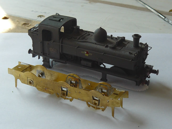 Here you can see the new frames assembled using the jig as described above. The placing of the hornguides and bearings in the front and centre axle positions should be clear from the picture. The bearings will ride vertically in the horn guides allowing the axles to move up and down, but that movement will be controlled by the compensating beam that will be described shortly. The rear axle is in fixed bearings and does not move; this will be driven from the motor and gearbox.
The "legs" that the frames are resting on are, in fact, the guard irons; these will be bent to the correct shape and aligned with the wheels once the latter are fitted. However, before the wheels can be fitted, it is better to install the other things that need soldering as the steel tyres and corrosive fluxes don't make happy bed fellows! It is also more convenient to paint the frames before the wheels are fitted. The locomotive body, now permanently detached from its original OO chassis, is seen in the background. A certain amount of fettling of the frames was required to ensure a nice snug fit between the bufferbeams. It will also be necessary to fix some cross members inside to provide attachment points for the new frames. The various holes in the side frames are for the brake hangers and the pivot for the compensating beam. |
|
| Frames Stage 2 |
| |
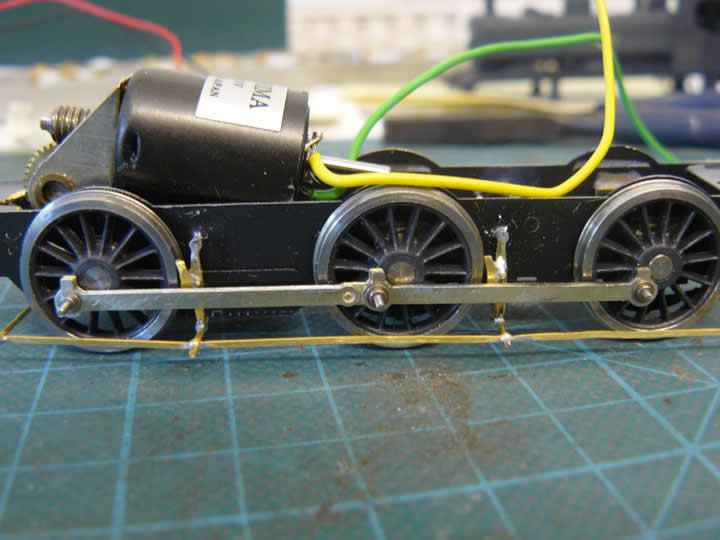
 The brake hangars and compensating beam have been installed; you can see the latter between the front and centre axles. It is designed to rotate about the pivot positioned between the frames, and the beam will rest on the axles. If one axle rises, the beam presses the other down thus ensuring contact is maintained between wheels and track. The section of the brake hanger wire, which passes in front of the beam pivot, will be removed from between the frames to allow free movement of the compensating beam.
The frames have been given a coat of grey primer, using a spray can from the local motor spares shop; the hornblocks have been masked off to prevent paint impeding their free movement in the guides. The paint will have to be scraped off the brake hangars before the brakes are fitted as solder does not work on paint! This highlights one of the infinity of logistical conundrums of building models - it would have been handy to solder the brakes in position prior to painting, but to do this means fitting the wheels which makes painting difficult. But now, of course, the brakes have to be soldered in close proximity to the steel tyres on the wheels - not ideal, but there are ways to minimise the problem as will be explained in due course. Solving these little riddles is all part of the challenge of building models. After this picture was taken, the chassis was sprayed matt black, the final job prior to fitting and quartering the wheels. |
|
| Quartering |
| |
 Steam locomotives need the crank pins on each side offset relative to one another by 90°, or one quarter of a circle - hence the term "Quartering". Some axles come with square ends and are self quartering, but many - such as Gibson and Ultrascale - have to be quartered by hand. This job is nowhere near as daunting as it sounds, provided you proceed methodically and carefully. There are various jigs available but in my experience they are more hindrance than help.
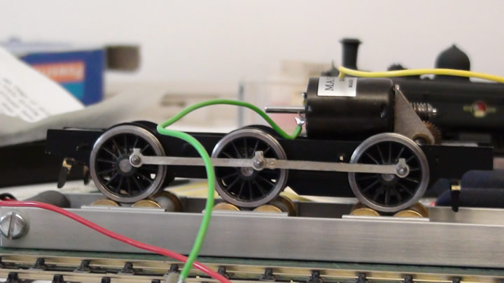
Starting at one end of the chassis, the first axle is quartered by eye; in truth, achieving an exact 90° is not necessary as both sides cannot be seen at once and, provided any slight inaccuracy is consistent on all axles, the mechanism will work, though of course we do try to be as precise as possible. At this stage ensure that the wheels are square on the axle ends, and the correct distance apart using a back-to-back gauge appropriate to your chosen scale. This first axle now becomes the datum and should not be adjusted subsequently. Then install the next axle, quarter that by eye and fit the coupling rods to both sides; these should not be a tight fit on the crank pins. Adjust the second wheel set until the mechanism runs smoothly as an 0-4-0; there should be no "lumpiness" to the motion as you push it gently along a piece of track - do not try to turn the wheels on a compensated chassis unless it is on some track or a rolling road, or the mechanism is likely to jam. When this is running smoothly, the second axle should not be adjusted again. Now add the next wheel set and repeat as above, proceeding to a fourth or fifth axle as required for the locomotive you are building. Provided you have built the frames square and your rods are not a tight fit on the crank pins, achieving a smooth, free running mechanism is very straightforward. Do, however, remember to install the gearbox with the appropriate axle before you quarter it! Don't ask... The picture shows the Pannier frames with wheels quartered (and motor and gearbox installed!) on the rolling road, with wires temporarily connected direct to the power supply. |
|
| Brakes - 1 |
| |
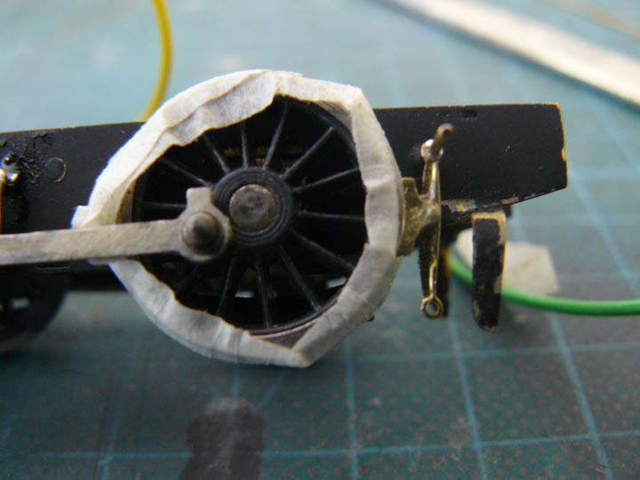 As noted earlier, soldering the brakes after the wheels have been fitted and quartered is not ideal. There are a couple of ways round it. The first is illustrated here - cover the steel treads of the wheels with masking tape prior to soldering; it is a bit fiddly, and I could not guarantee that excessive flux would not soak through the tape, but it works for me. An alternative is to use a less corrosive resin flux; I do find, however, that the solder does not flow so well with resin and there is a tendency for it to form blobs - the last thing you want on tiny components like these. You could, of course, resort to an adhesive such as super glue; this, I find, sticks only my fingers (hardly surprising given it was originally designed to seal battlefield wounds) and little else, so I avoid it where possible! Still, you pays your money and you takes your choice...
The added advantage of using tape is that it does give a gap between the brake block and the wheel tread; you will need to clean the tread thoroughly to remove any sticky residue from the tape The guard irons have now been bent to shape; as can be seen, some of the paint has chipped off in the process. Paint seems exceedingly reluctant to adhere to brass, whatever primer is used - even etch primers seem unable to give 100% reliable coverage. However, it will be an easy job to touch this up when the brakes and pull rods are painted. |
|
| Brakes - 2 |
| |
 The brakes and the pull rod have been soldered in position and the masking tape removed. The brake on the centre wheel needs a tweak to prevent it rubbing against the wheel which would cause undesirable friction and a short circuit!
The brake hangers and rodding are supposed to be attached to 0.45mm wire; I have found this to be very flimsy, especially when handling locomotives at an exhibition, so risked drilling out the brakes and rods to 0.7mm. There wasn't much brass left round the holes, but I got away with it and, now soldered, the unit feels very much stronger. Now everything is secure, the excess length of the crank pins and brake hanger wire can be trimmed off and the brake assembly painted. |
|
| The next stage |
| |
| We are approaching the home straight! All that remains, once the brakes are painted, is to fix some brass plates inside the body to form attachment points for the chassis, fit pickups and put her through a final test. |
|
| A Quick Conversion |
| |
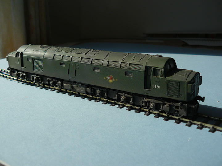 One of my modelling friends and diesel enthusiast, Clive Mortimore, acquired a Modern Outline Kits EE Type 4 (Class 40); unfortunately for him it had been built in P4. However, I had built mine in OO many years ago before I switched to P4, so a bogie swap was hastily arranged. This must be one of the quickest and simplest P4 conversions ever - pity they are not all so simple!
D326 is pictured shortly after return from the Works riding on the replacement bogies. Miraculously, even the weathering on the bogies matched the rest of the underframe! D326 was something of a celebrity, having been the locomotive in the Great Train robbery when £2.6 million was taken in an armed raid in August 1963. |
|
|
|
 |
|