| This chapter is about the design and installation of the electrical systems in the layout. Early planning and design of the electrics is vitally important and is best done before any track laying commences. This will allow adequate isolating sections to be incorporated - these will be a major requirement for the shed. A layout such as this is an ideal candidate for DCC - this would obviate the need for much of the complexity of wiring required. I think DCC is a fantastic development, particularly the provision of sound, which adds a whole new dimension to a layout. However, I am not sure I am ready to commit the time and cost required to convert to DCC, but I shall enjoy watching and listening to DCC equipped layouts at exhibitions! Being reasonably familiar with electrics, the wiring holds no terrors; I hope that the following will help take some of the mystery away for others. |
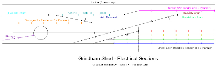 Having completed the track planning, a design for the electrical sections was drawn up as can be seen, again using CAD - such a worthwhile investment. This is based on a simple schematic of the track, with isolating sections added. These are of two types - isolating the common crossing to allow for the polarity to be switched when the points change, and simple isolating sections to allow locomotives to be stored at various locations on the layout.
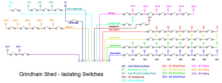 This is the partially completed wiring diagram for the isolating switches required for the layout. I have used the colour scheme adopted previously for each section of the layout. This will make it easier to trace any wiring problems in due course