|
|

|
| Chapter
1: Planning & Design |
| |
| This chapter in the Story of the Evolution of a Layout describes some of the stages in the planning and design process. As with any project, careful planning will reap rewards and avoid most of the pitfalls that await those who just rush in; giving prior thought to design will, hopefully, result in a railway that is part of its environs, rather than some track with scenery added. |
| |
| The Concept |
| |
| My main interest in model railways is building locomotives and a Running Shed has always been an attractive idea as a showcase for the models. The problem is that to make it worthwhile requires a decent stud of suitable motive power; as a P4 modeller, acquiring that is more than a few visits to the model railway shop. Still, over the years, the fleet has grown and a decent sized shed scene now, at last, seems more achievable. Peter Howell, my collaborator on Grindham, is a very enthusiastic builder of structures and scenery and the requirements of a shed scene present some considerable challenges in that area and so, with the retirement of Grindham, we decided to embark on a new layout to be based around a running shed. Given the existing stock of locomotives, together with our predilection for things Great Western, a GW area shed was inevitable; that it should be Grindham Shed, entirely predictable. Careful planning would be essential to ensure that we achieved something that would not only follow prototype practice, but also accommodate the various locomotives, including large 4-6-0 and 2-8-0 types. As the layout would be built to P4 standards, and all the track would have to be hand built, careful planning and design would be especially important; P4 can be very unforgiving! The stages we went through are documented below. P4 is not everyones' cup of tea, but the stages and processes described here are equally applicable to any model, irrespective of gauge and scale |
|
| Survey the Site |
| |
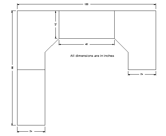 The first stage was to draw an accurate plan of the baseboards that had previously been built to fit the model railway room. This is essential to ensure that the proposed layout will fit the space available - what one hopes to achieve is not necessarily practicable, as will become clearer as this saga unfolds. The drawing was done using DesignCAD, a very reasonably priced CAD package from IMSI. Of course, there is nothing wrong with pencil, paper and rule if you have no desire to use CAD, but it does have several advantages - one of which is that the design and its dimensions can easily be exported for use by other computer systems, of which more anon.
The drawing shows the board outlines, which delimit the available real estate. The dimensions are in inches - I am too long in the tooth to think in metric! CAD makes it an easy matter to convert to metric when the need arises - another great benefit. |
|
| Running Shed |
| |
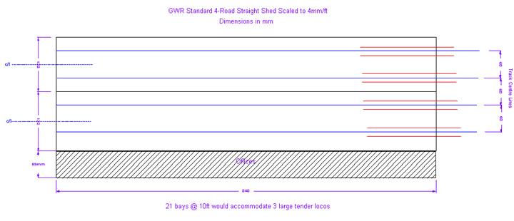 To represent an authentic locomotive depot in a model requires the main structures to be present. These include the shed building itself (including the offices), a coaling stage and turntable and so the next stage was to draw accurate floor plans. The dimensions for the shed building were taken from a drawing in Lyons's "An Historical Survey of Great Western Engine Sheds 1947" - an invaluable work of reference which is, sadly, long out of print. The dimensions for the shed building were taken from the example still standing at Didcot in Oxfordshire.
Using the trusty CAD package, the floor plans were drawn to scale, with track centrelines included to assist with proper alignment at a later stage as can be seen in the accompanying illustration. Another advantage of CAD is that the drawing can be built up in layers so that things such as the dimensions and labels can be kept separate from the outline; this makes it so much easier for subsequent use, where details other than the drawing itself would be spurious. |
|
| Coaling Stage |
| |
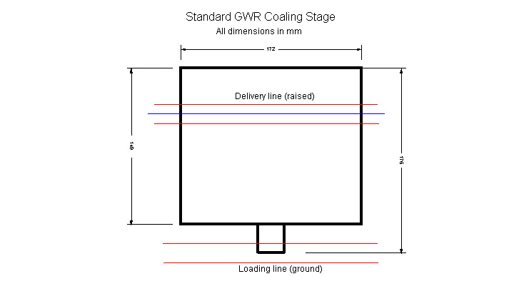 The classic Great Western coaling stage was a very distinctive structure. It was usually brick built with a large water tank on the roof. Coal wagons would be propelled up an incline to its upper level, the coal being discharged to this area. It was then loaded into tubs that were pushed out onto a platform and the contents tipped into the tender or bunker of a locomotive on the line below.
This drawing of the floor plan has the dimensions in millimetres; this is in preparation for use with some clever software for drawing track which we will meet shortly. Further scale drawings will be required in due course for construction of accurate models of the structures, but we are a long way from that! |
|
| Coaling Stage Incline |
| |
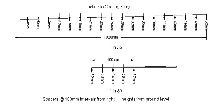 According to Lyons, the slope to the Coal Stage was 1 in 35; it was a simple matter to construct a 1 in 35 slope in DesignCad. By setting the vertical distance equivalent to the height of the upper level of the coaling stage (52mm), the horizontal distance to ground level (0mm) could be read off, without the need to recourse to Pythagoras or trigonometric functions; this distance (1820mm) is essential to ensure the Coaling Stage is positioned correctly.
By adding vertical lines at 100mm intervals to represent supports, the CAD package was then used to read off the dimensions of each support for use in subsequent construction. The process was repeated for the 100 ft (400mm) at 1 in 80 beyond the stage. |
|
| Turntable |
| |
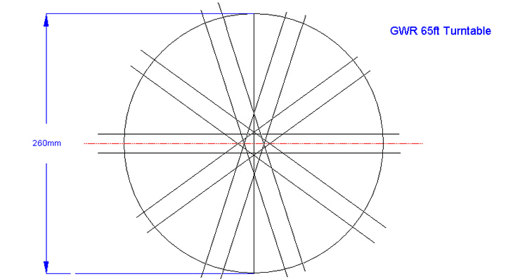 A turntable is the final essential structure required for a running shed. Most Great Western sheds of any size would be equipped with a standard 65ft diameter table. To draw the outline in CAD was simple; it also includes a useful feature to replicate lines and space them equidistantly around a circle as in the accompanying illustration. This indicates some of the possible positions of the bridge, which was useful for trying various ideas for the layout.
The whole "turntable" can then be rotated on screen and the track with the centre-line used to align potential approach tracks. This drawing was combined with those of the shed and coaling stages and the baseboard outlines so that preliminary designs of the shed area could be made. |
|
| Initial Sketch |
| |
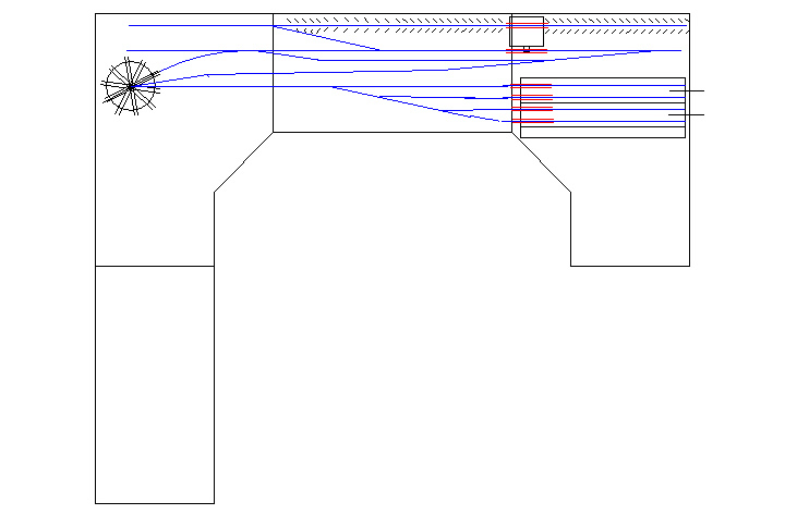 In addition to plans of the structures, the Lyons volume includes the layout of all GWR sheds as they appeared in 1947 and so is a useful reference when attempting to recreate a realistic model. Unfortunately (but not unexpectedly), none of the major sheds would fit into the space available and, as is usually the case, the model must make compromises. This has meant assuming that large areas are "off scene", as will become apparent later.
The drawing is a very early sketch of the proposed layout and, although it differs significantly from the final design, it nevertheless incorporates all the main features - the 4 road straight shed, the coaling stage with ramp and a 65ft turntable. The scale "footprints" of the structures were essential to ensure that they fitted in; use of CAD means they can easily be moved around and repositioned while various ideas are tested. You may have noticed, for example, that the shed here has been rotated through 180 degrees from the original CAD drawing and the turntable rotated about its centre to align a potential approach track. Limitations on practical curvature meant that one idea, for a hidden track from the unused board to the shed, proved impractical and had to be abandoned. This board has been set aside for scenic development and will feature an urban scene to help put the shed in context. |
|
| Introducing Templot |
| |
 Sketching out a track plan is one thing; prototype track is quite another and I am not one of those talented people who can visualise and accurately sketch a dimensionally correct section of track. Happily there is a wonderful software tool that more than compensates for this deficiency - Templot. Templot produces track templates - in every conceivable scale and gauge - which can be laid out on screen to build up a track plan that conforms to prototype practice. It will produce templates for plain track, turnouts, crossovers and so on with just a few clicks of the mouse; these can then be manipulated to the required size and curvature, and Templot will manoeuvre them into position, maintaining correct alignment between adjoining templates and the correct spacing between adjacent ones. These can then be printed out full size ready for track construction.
 Templot not only generates a template for any conceivable piece of track, it also allows the shapes of baseboards and structures to be included; these can be drawn using Templot, or imported from CAD or from scanned drawings. This makes it easy to align tracks with structures and to check for adequate clearances as well as the all important consideration of whether the track will fit in the space available Templot costs less than most ready to run locomotives, and is a very worthwhile investment. Usual disclaimers apply - I have no connection with Templot other than as a very satisfied customer. To find out more, go to the Templot web site. |
|
| The Layout in Templot |
| |
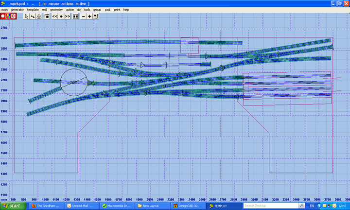 This is a screen shot of the track plan as created in Templot; the CAD sketch was imported and used as an initial guide to position templates. It takes only a few clicks with the mouse to generate a complete template such as a turnout, which can then be curved or otherwise manipulated and manoeuvred into the required position. Impracticalities in the original concept soon became very clear! Templot warns when curvature is below a recommended minimum, a particularly useful feature when working to an exact scale like P4. Templot will correctly join and align various templates whilst maintaining correct spacing between adjacent tracks, make transition curves and perform many other functions to ensure an accurate representation of the prototype.
 Although not obvious here, the turnouts have correct Great Western style curved switches - the assumption being that under BR ownership any renewal at a shed would have re-used recovered GW track rather than new items following the REA practice adopted after nationalisation. Note the sleepers have been omitted from the shed roads where there will be inspection pits, and the ash roads where there are also pits and the area will be paved. Templot also enables movement of the structures to the desired location and orientation - you can see, for example, that the shed, originally drawn in DesignCAD, has been rotated slightly from the horizontal. The track centre lines from the original CAD drawing have been used to align the shed roads. The turntable was re-drawn using Templot instead of the original CAD version; this ensured precise alignment of the approach and exit tracks with the turntable bridge. |
|
| Templot Track Details |
| |
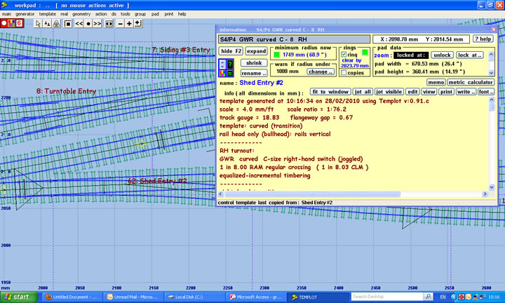 This screen shot illustrates the track templates in more detail - using Templot's "zoom" function. I have expanded the information panel to show some of the details about one of the templates - in this case, one of the turnouts. There is much more information available, as indicated by the scroll bars. The data provided help ensure that there are no over-tight curves, that headshunts and sidings are adequate and so on; because everything is still in the computer, adjustments can easily be made to avoid potential problems - better now than when the track is built!
When the templates are printed out full size, they are used as the basis for building the track. The templates are fixed accurately in situ on the baseboards so that construction can begin; additional copies of templates can be printed to allow construction of point and crossing work to be undertaken at a work bench, for subsequent installation at the appropriate location |
|
| The Final Plan |
| |
 The board outlines, structure plans and the rough CAD sketch were exported to Templot and used as a guide to lay out templates as described earlier. The limitations imposed by following prototype track practice led to a radical rethink and to many more evolutions before a final design was reached.
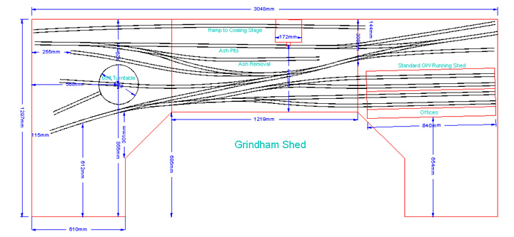
 This is the final plan for Grindham Shed. This drawing has been derived from the detailed track templates generated using the Templot software. The track outlines have been re-exported from Templot back to CAD in preparation for more detailed planning of the scenic areas, although the "empty" scenic board has been omitted from this illustration. As you can see, it differs significantly from the initial CAD sketch. This was due to the need to accommodate prototype switch & crossing geometry and curvature limitations, and also for practical considerations such as physical access to the various parts of the layout. It has only been possible to fit in part of the shed area; the entry to the coal stage incline and the run round loops for coal and ash wagons have been omitted, as have the storage sidings normally associated with a large running shed. This drawing has had key dimensions added; these are to ensure the track templates can be accurately positioned on the baseboards. |
|
| The Layout in Context |
| |
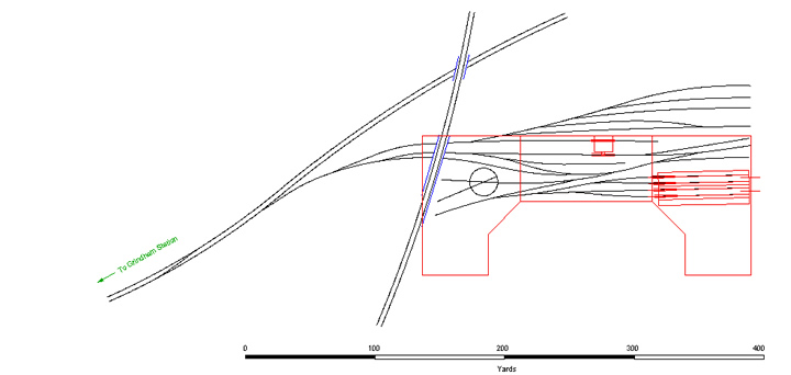 Part of getting an authentic layout is that it should be part of a scene, and that there is a reason for every feature. This shows the shed in context with the "off scene" area of the complex, as well as other features such as the railway line that will form the scenic break. This larger picture will help in evolving the design of the scenic parts of the layout which will occupy the empty spaces on the baseboards.The idea is that the shed is connected to the ex-GW main line, not too distant from Grindham station; the line that crosses the shed entrance on a viaduct is ex-LMS, which will give a perfect excuse for some ex-LMS locos to be seen "on shed".
 The extended track plan was, again, drawn in Templot and exported to DesignCAD. The different elements (track centre line, rails and background shapes) are in different layers and a new layer for "scenery" will be used eventually to plan roads and so on. The accompanying drawing shows only the track centre-line for clarity. The red outline delimits the model, and the additional scenery board has also been omitted I have included a scale to indicate the actual distances involved if this were a real location. |
|
| A Paper Layout |
| |
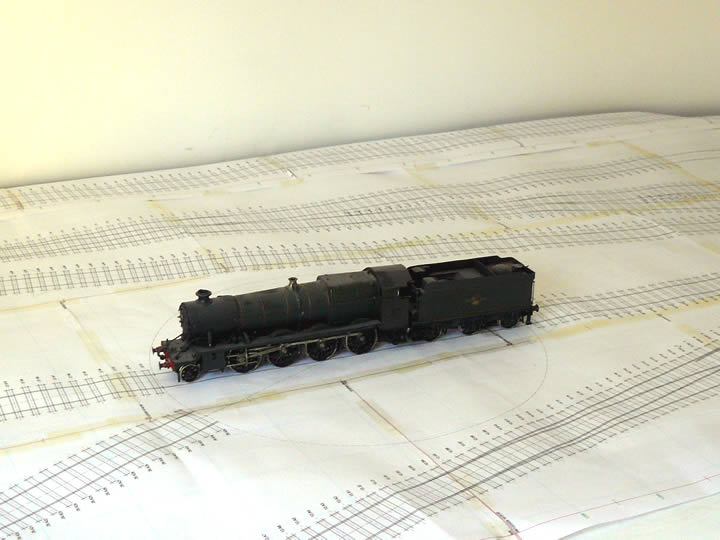 The full set of templates was printed from Templot and joined together to produce a track plan to see how things looked full size, and to check for accessibility, clearances and so on.
Here you can see part of the plan, roughly laid on top of the baseboards, with Churchward 47XX Class 2-8-0, No 4701, positioned on the turntable. This is the longest engine in the fleet - it is a tight squeeze but, if the Great Western could manage it, we will have to follow suit! Some of the full size Templot track templates can be seen; these give a clear indication of the correct position for the rails and timbering; not visible is the additional information provided, such as the location of rail joins, switch drive units and so on, not to mention the all important guide marks to ensure correct alignment of the individual sheets of paper with adjacent ones. Some adjustments were required, such as the position of the turntable to allow easier access, before the plan was finalised. |
|
| Next Step |
| |
| This is as far as we have gone with the planning. The next step will be to sketch out the plan of the urban area surrounding the shed. This is of relatively low priority. This Chapter will be updated in due course when there is further progress to report |
|
|
|
 |
|